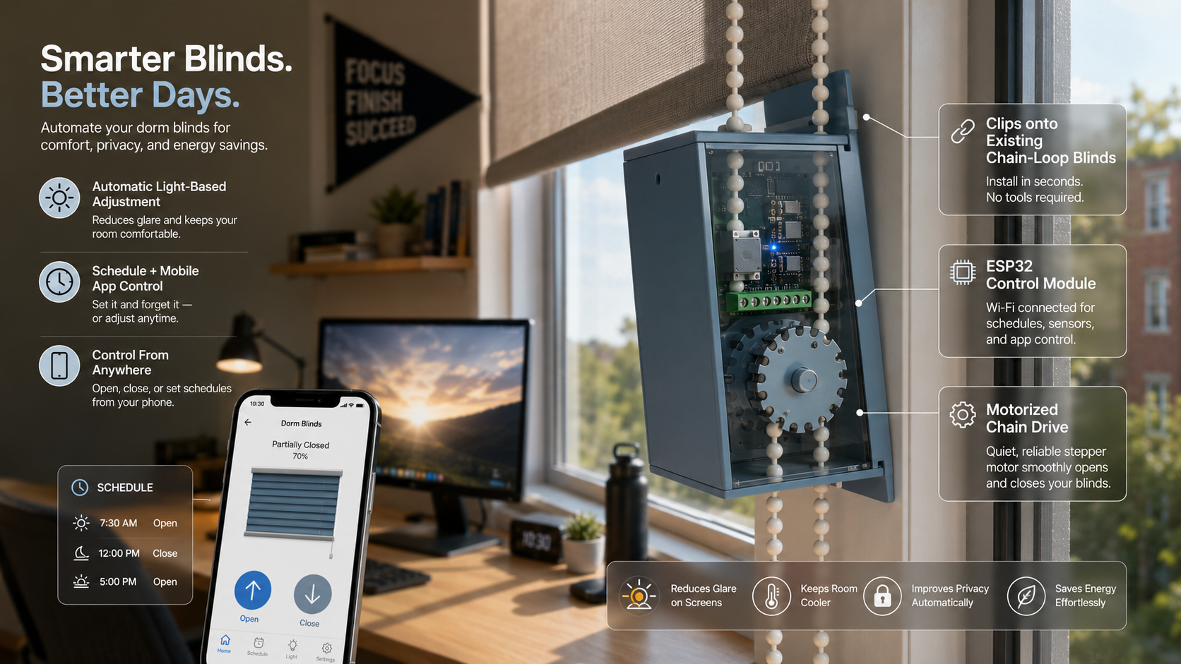
AI generated image
04 / Design & CAD
From sketch to enclosure.
3D modeled enclosure that mounts to existing blinds and contains the stepper motor, PCB, and gearing.
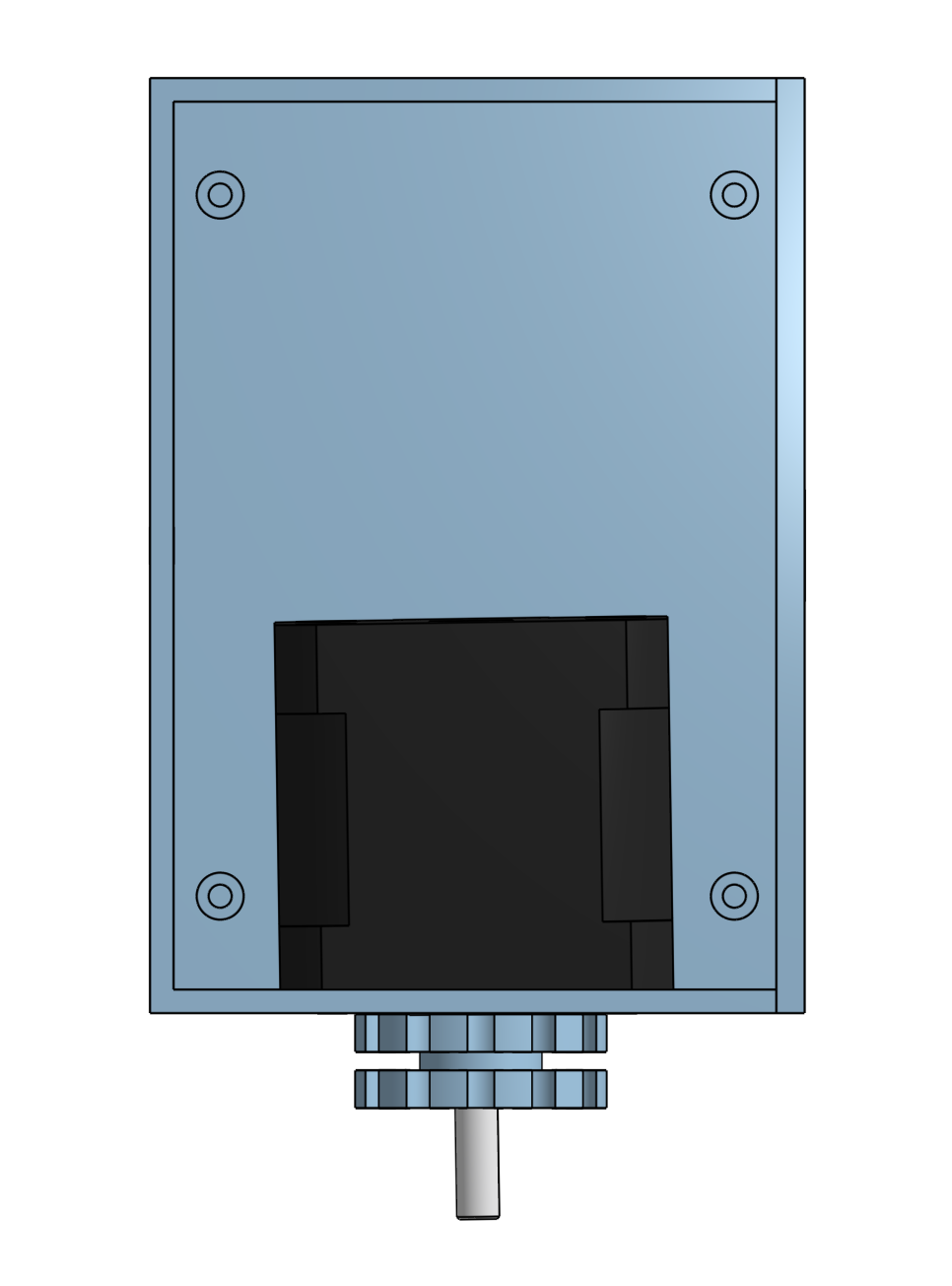 1Screw hole
2Motor
3Output gear
Fig 4.1 / Top view
CAD render of the enclosure showing the cavity for the stepper motor and the gear that drives the chain loop.
- 1M3 screw hole: used to hold the components in place
- 2Stepper motor cavity: black box visible on the back face
- 3Output gear & shaft coupling that engages the chain loop
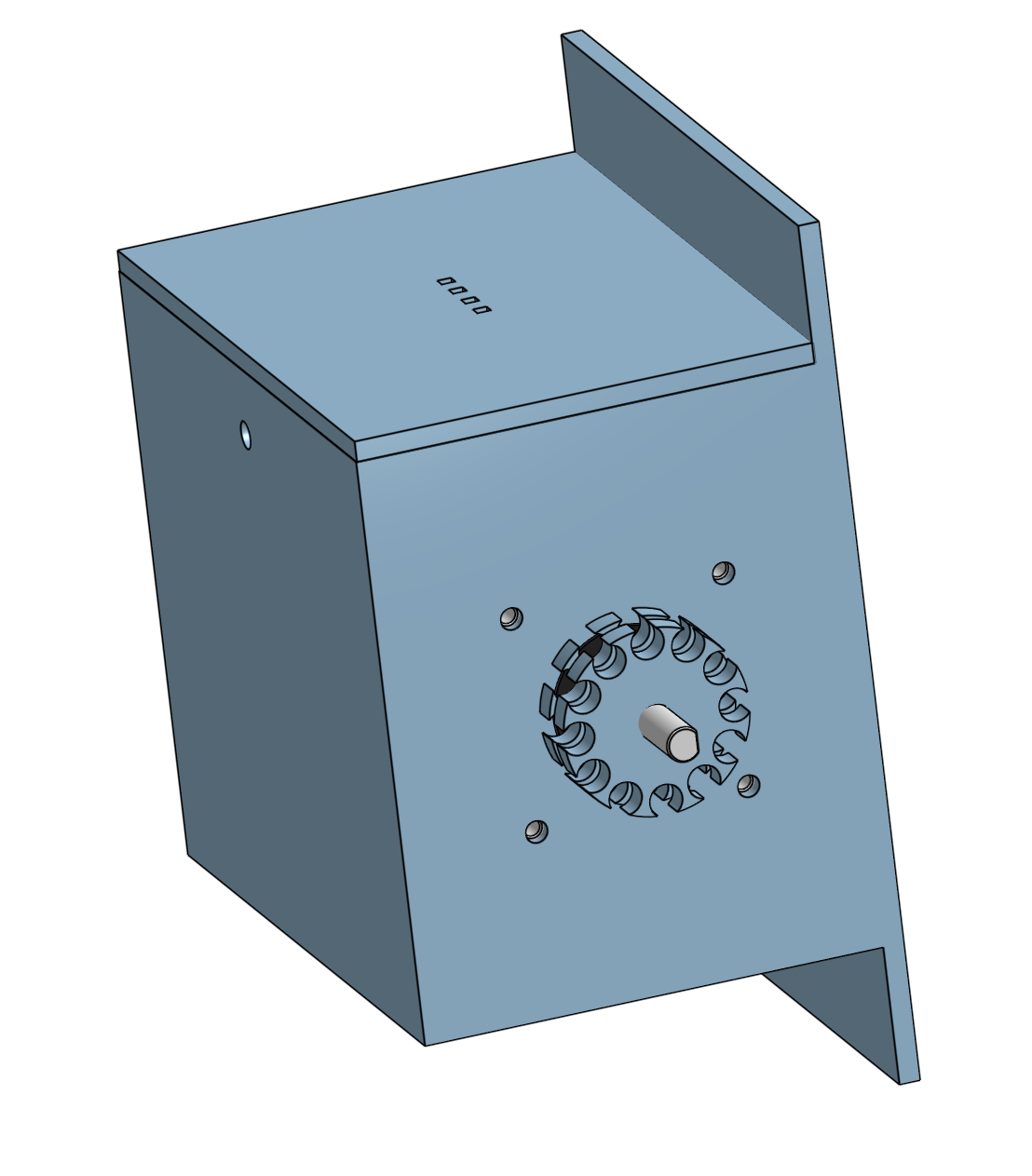 1Photoresistor port
2Sprocket
3Vent slots
Fig 4.2 / Isometric
3D view showing the photoresistor port (top), output gear face, and motor shaft.
- 1Photoresistor port: small slot on top face for ambient light sensing
- 2Output gear teeth: engages the chain loop on the user's existing blinds
- 3Ventilation slots: allows air to enter the enclosure and heat to escape
05 / Hardware
The actuator.
A NEMA 17-class stepper motor sized to drive the chain loop with controlled torque.
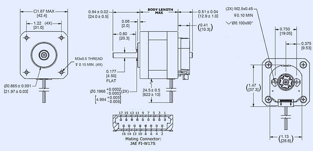
Fig 5.1 / Spec sheet
Mechanical drawing of the stepper motor.
06 / Testable Hypothesis
Testing our core idea.
If the AutoBlinds device is mounted on a standard chain-loop blind, then it should open and close the blinds shortly after receiving a command from the mobile app.
Hypothesis result
The prototype successfully opened and closed using phone commands, supporting our
hypothesis that AutoBlinds can control a standard chain-loop blind quickly after
receiving an app command.
06 / Block diagram
How everything you just saw interacts with each other.
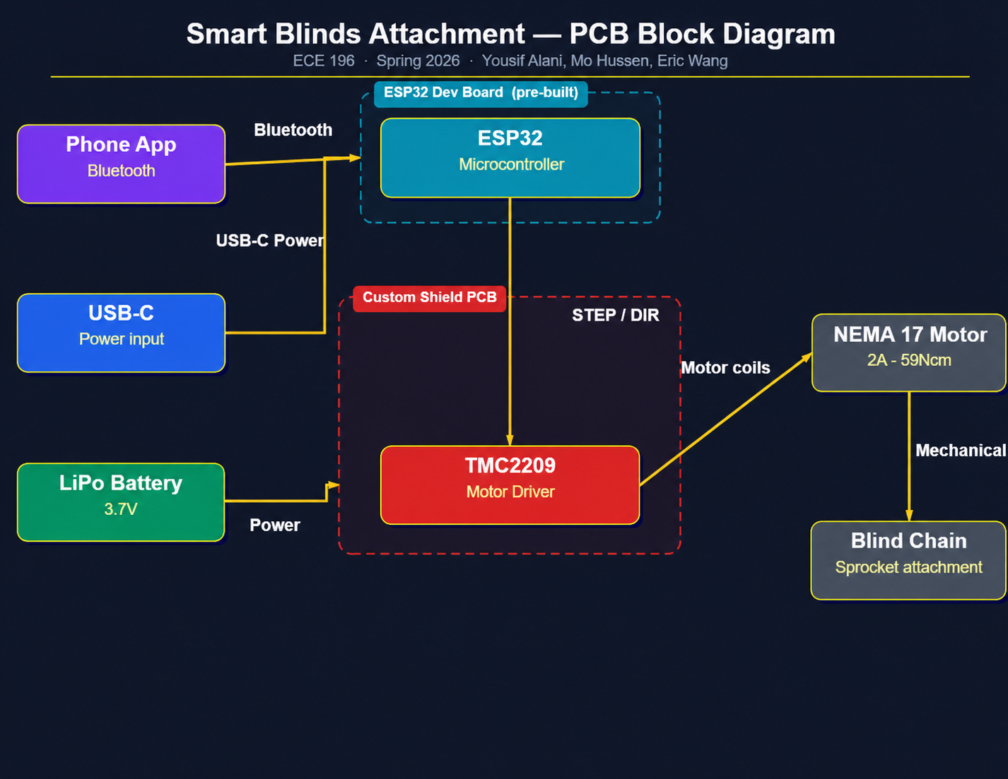
Fig 6.1 / Block diagram
High level system architecture.